
Tin-plated copper busbars are essential conductive components in modern electrical systems. They provide a compact and dependable path for current transmission while simplifying the assembly of switchgear, control cabinets, battery systems, industrial equipment, and new energy applications. By combining the electrical conductivity of copper with the surface protection of tin, this type of busbar helps support stable connections in environments where oxidation, repeated assembly, humidity, and long-term electrical loading may affect untreated copper.
A busbar is more than a simple strip of metal. Its dimensional accuracy, material selection, surface condition, hole position, flatness, edge quality, and connection design all influence the safety and reliability of the finished electrical system. A well-designed busbar can reduce wiring complexity, improve current distribution, support efficient assembly, and contribute to a cleaner internal layout. A poorly manufactured busbar may create alignment problems, unstable contact, excessive resistance, installation delays, or premature maintenance requirements.
For these reasons, buyers increasingly require customized tin-plated copper busbars produced from engineering drawings, three-dimensional models, samples, or application specifications. The manufacturing supplier must be able to support tooling development, precision stamping, CNC processing, bending, threading, welding, riveting, surface treatment, inspection, packaging, and production scaling. Zhejiang Taoyang Electronics Co., Ltd. provides these capabilities for customers in relay manufacturing, electrical equipment, current transformers, energy storage, automotive electronics, and new energy applications.
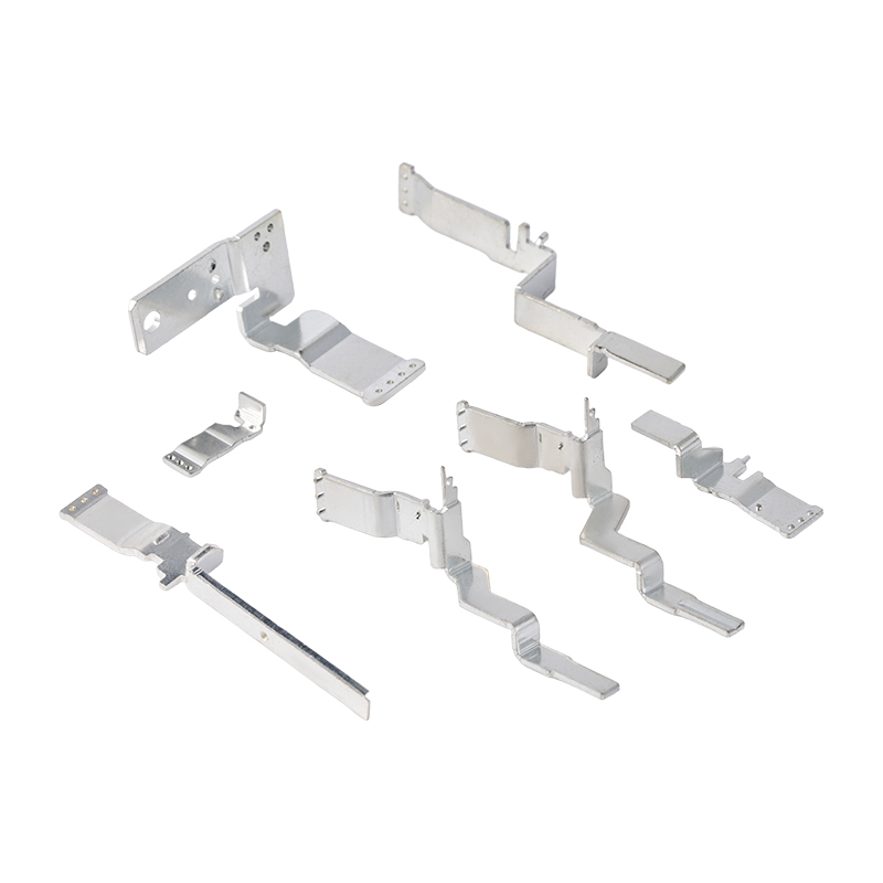
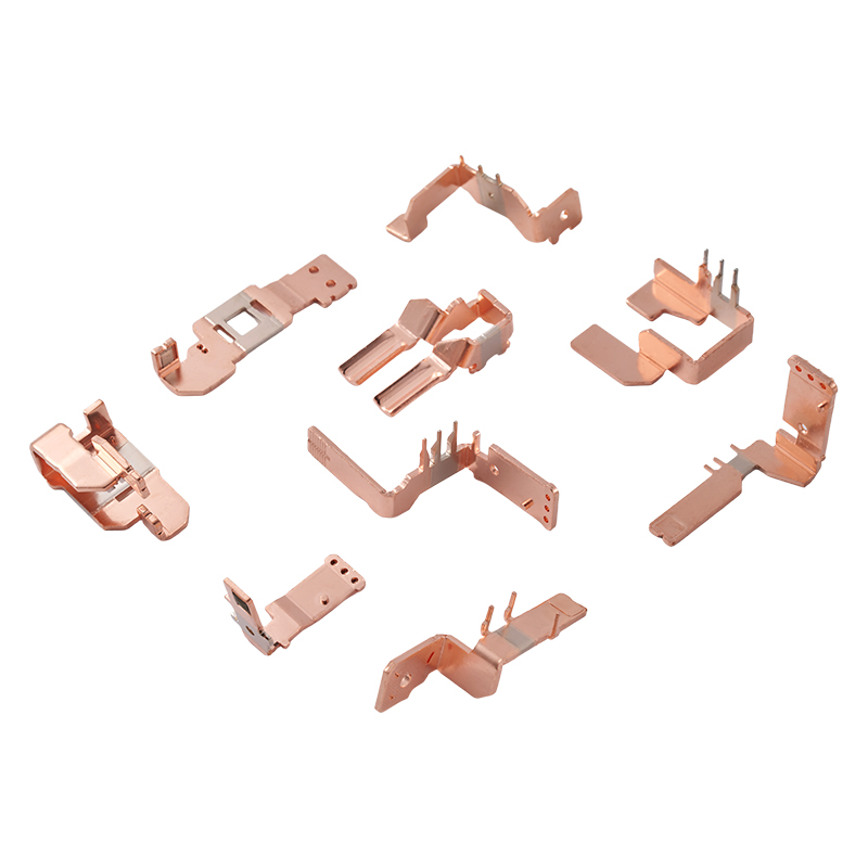
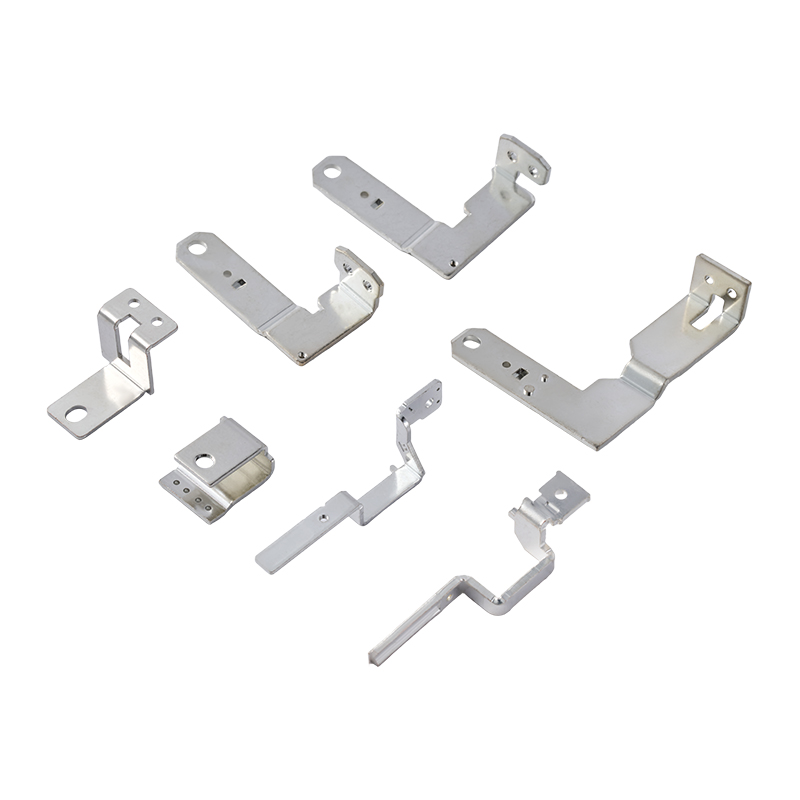
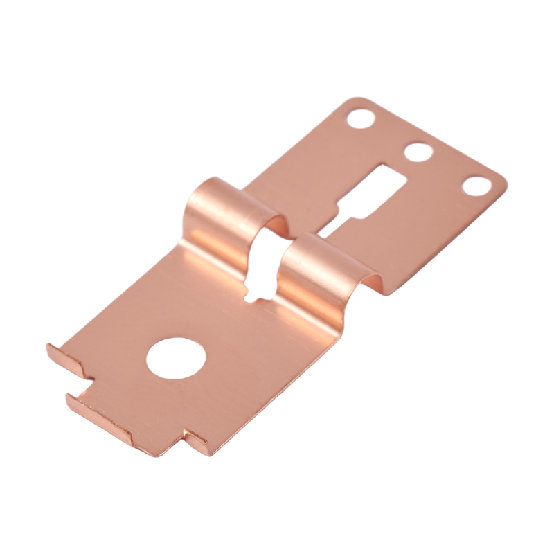
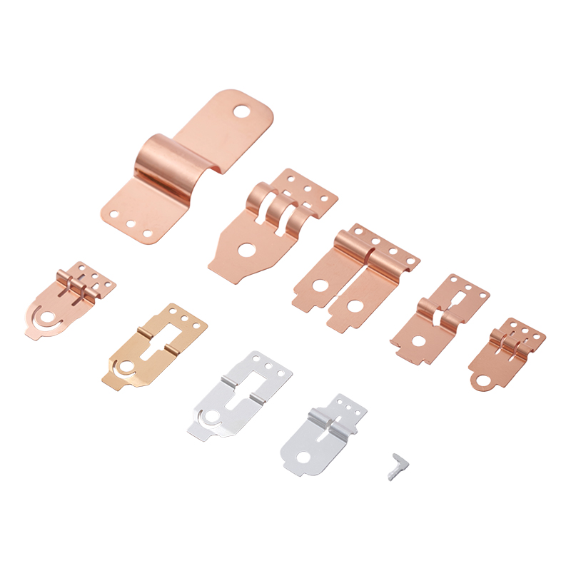
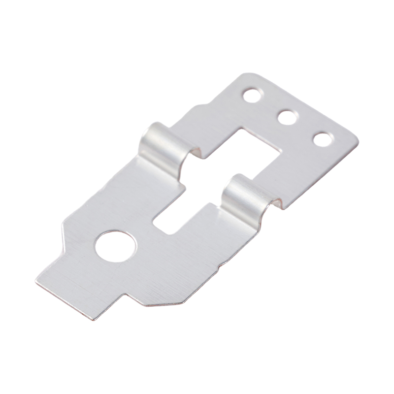
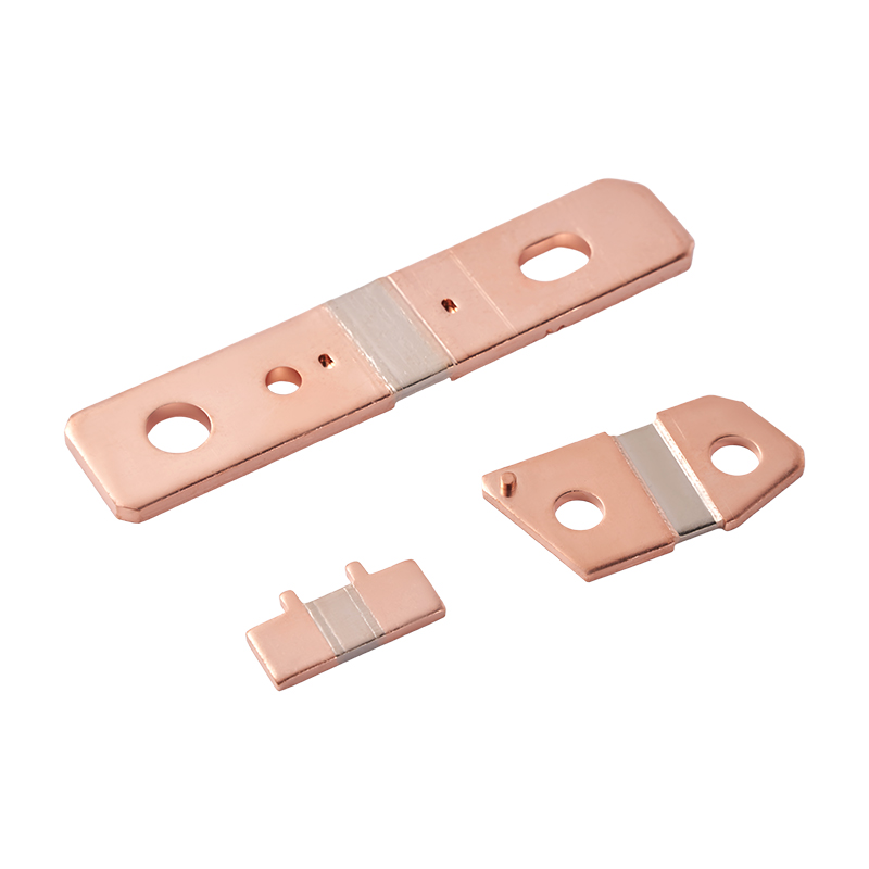
A tin-plated copper busbar is a conductive copper component covered with a layer of tin on its surface. The copper base provides efficient electrical conductivity, while the tin coating helps protect the surface from oxidation and supports more stable contact performance. Depending on the application, the busbar can be manufactured in a flat, bent, slotted, perforated, stepped, or three-dimensional configuration.
Unlike ordinary insulated wire, a busbar is usually a rigid conductive part designed to carry and distribute current through a defined mechanical structure. It may contain mounting holes, threaded sections, connection tabs, embossments, slots, bends, or welded features. The design is normally developed to fit a specific electrical enclosure, relay structure, battery module, power distribution unit, or control assembly.
The tin-plated surface is particularly useful where the copper busbar must be connected to terminals, fasteners, contact plates, or other conductive parts. Copper naturally develops an oxide layer when exposed to air. Although copper remains highly conductive, surface oxidation can affect contact consistency and increase the risk of connection instability in certain operating conditions. Tin provides a protective and solderable surface that is widely used in electrical and electronic applications.
The final performance of the busbar depends on the complete product system rather than the plating alone. Copper grade, thickness, cross-sectional area, thermal conditions, plating quality, joint design, fastening force, surface cleanliness, and installation method must all be considered. A qualified manufacturer therefore evaluates the component according to the customer’s drawing and operating requirements instead of treating every busbar as an identical standard item.
Copper is widely selected for busbar production because it offers a strong balance of electrical conductivity, mechanical workability, thermal performance, and availability. Compared with many alternative conductive metals, copper can transmit substantial current through a relatively compact cross-section. This helps engineers save installation space and reduce the amount of material required for complex electrical assemblies.
Copper is also suitable for stamping, bending, punching, machining, and other forming processes. This makes it possible to manufacture busbars with integrated connection features instead of combining several separate parts. A customized copper component may include mounting holes, bends, slots, tabs, stepped sections, or formed contact areas. Such integration can reduce the number of fasteners and assembly operations in the customer’s product.
Another benefit is copper’s thermal conductivity. Electrical current produces heat, especially in high-current applications. A properly sized copper busbar can help transfer heat away from the connection area and support the thermal design of the equipment. Nevertheless, engineers must still verify current capacity, temperature rise, ventilation, spacing, and enclosure conditions for each application.
Pure copper and T2Y2 copper are common choices for conductive parts. Beryllium copper and phosphorus bronze may also be considered where the application requires a different balance of strength, spring performance, wear resistance, or forming characteristics. The suitable material depends on the product design and cannot be determined by conductivity alone.
Tin plating helps reduce direct exposure of the copper substrate to air and moisture. This protection can be valuable in switchgear, electrical cabinets, battery systems, and industrial equipment where the component may operate for long periods under changing environmental conditions.
Surface protection is especially important at electrical interfaces. A clean and stable contact surface supports more predictable connection behavior than an untreated surface that has accumulated oxidation, contamination, or handling marks. Tin plating does not eliminate the need for correct joint design, but it provides an additional protective layer within the connection system.
Many busbars are secured by screws, bolts, terminals, rivets, or other conductive fasteners. The tin-plated surface provides a practical contact finish for these interfaces. When the mating parts, fastening pressure, surface condition, and plating specifications are properly controlled, the completed connection can maintain stable performance during normal operation.
Stable contact is important in relay assemblies, power distribution units, battery connections, and electrical control systems. Even small variations in contact resistance can become significant when current is high or when the equipment operates continuously. A suitable plated surface helps the manufacturer and equipment designer build a more consistent connection structure.
Tin is commonly used in electrical and electronic manufacturing because it is compatible with a variety of connection and assembly methods. Depending on the design, tin-plated busbars may be integrated with bolted, riveted, welded, crimped, or solder-related structures. The exact process must be selected according to the copper grade, coating specification, thermal requirements, and customer assembly method.
The plating thickness and method should be defined during engineering review. Different applications may require different surface specifications, and a busbar used in a high-humidity environment may require a different protection strategy from one installed inside a sealed electrical cabinet.
Power distribution cabinets and switchgear use conductive components to route current between incoming supplies, circuit protection devices, breakers, terminals, and outgoing circuits. A customized busbar can replace multiple lengths of cable and create a more organized internal structure.
Busbars used in these systems must be designed with adequate clearance, creepage distance, mounting support, and current capacity. Hole positions and bends must correspond accurately with the cabinet layout. A mismatch of even a small amount may affect installation efficiency, particularly when multiple busbars must be fitted in a confined space.
Industrial control panels contain relays, contactors, terminals, power supplies, controllers, and protective devices. Tin-plated copper busbars can be used for power distribution, grounding-related structures, terminal interconnections, or internal conductive links.
In these applications, a clean and compact busbar design may reduce wiring congestion. Fewer loose wires can simplify inspection and maintenance while helping improve the visual organization of the panel. Customized punched holes, threaded sections, and bent profiles allow the busbar to follow the equipment architecture.
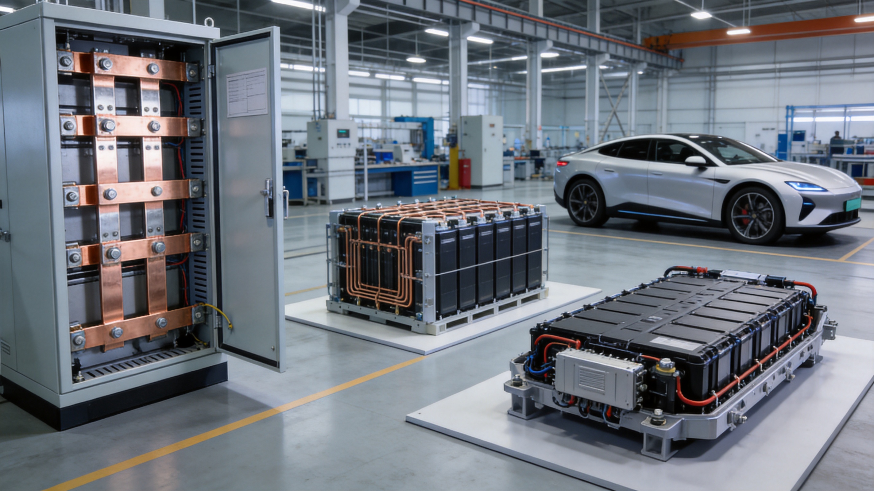
Battery energy storage systems require dependable current paths between cells, modules, packs, contactors, fuses, disconnect devices, and power conversion equipment. Busbars can be manufactured in configurations that fit the available space and match the required connection pattern.
Energy storage applications place particular emphasis on current capacity, temperature rise, electrical isolation, vibration resistance, and assembly consistency. The busbar must be correctly sized and securely fastened. Where the busbar connects to battery terminals or module components, the contact area and hole geometry must be carefully controlled.
New energy vehicles use conductive interconnection parts in battery packs, power distribution units, charging systems, inverters, and other high-voltage electrical assemblies. Weight, space, vibration, thermal conditions, and production repeatability are important considerations.
A stamped or formed busbar can combine several functions into one component. It may include connection holes, positioning features, bent sections, and contact surfaces that reduce the need for secondary assembly parts. The final design must comply with the vehicle manufacturer’s electrical, mechanical, environmental, and quality requirements.
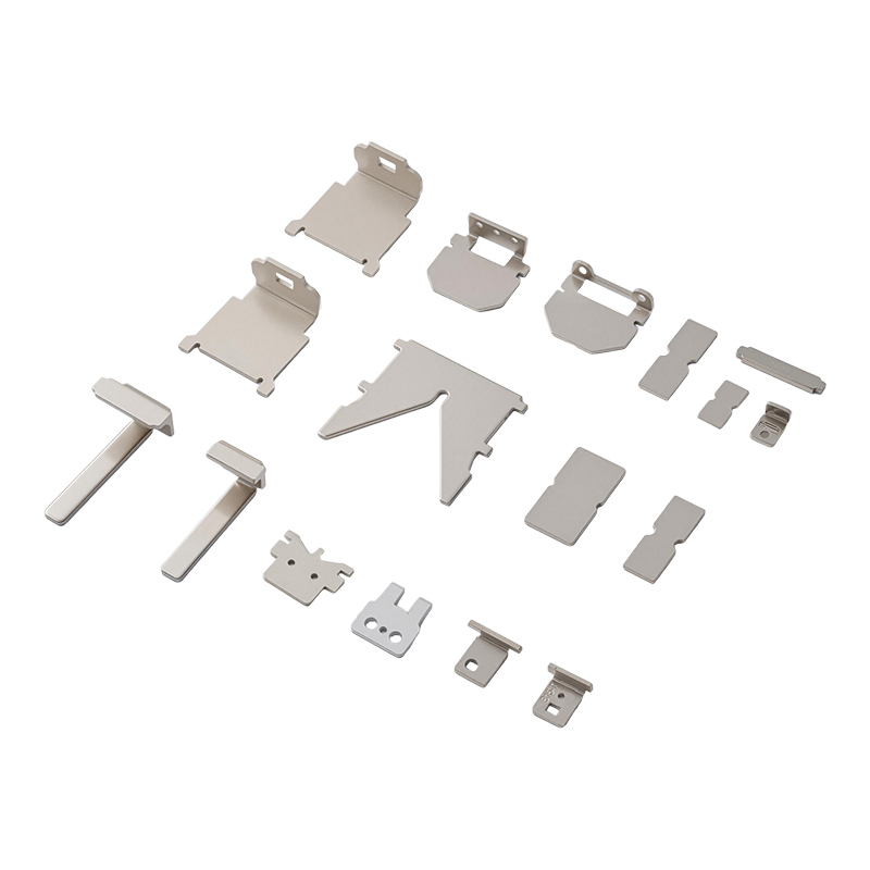
Relays and related electrical components require small, precise conductive parts that fit within carefully controlled assemblies. Although not every relay component is a large busbar, the same manufacturing principles apply: accurate tooling, consistent material thickness, controlled forming, clean edges, reliable plating, and thorough inspection.
For relay and connector OEM buyers, a supplier with experience in stamping hardware can provide more than a basic cut metal strip. The supplier can help develop integrated parts that combine conductive, mounting, and mechanical functions within one component.
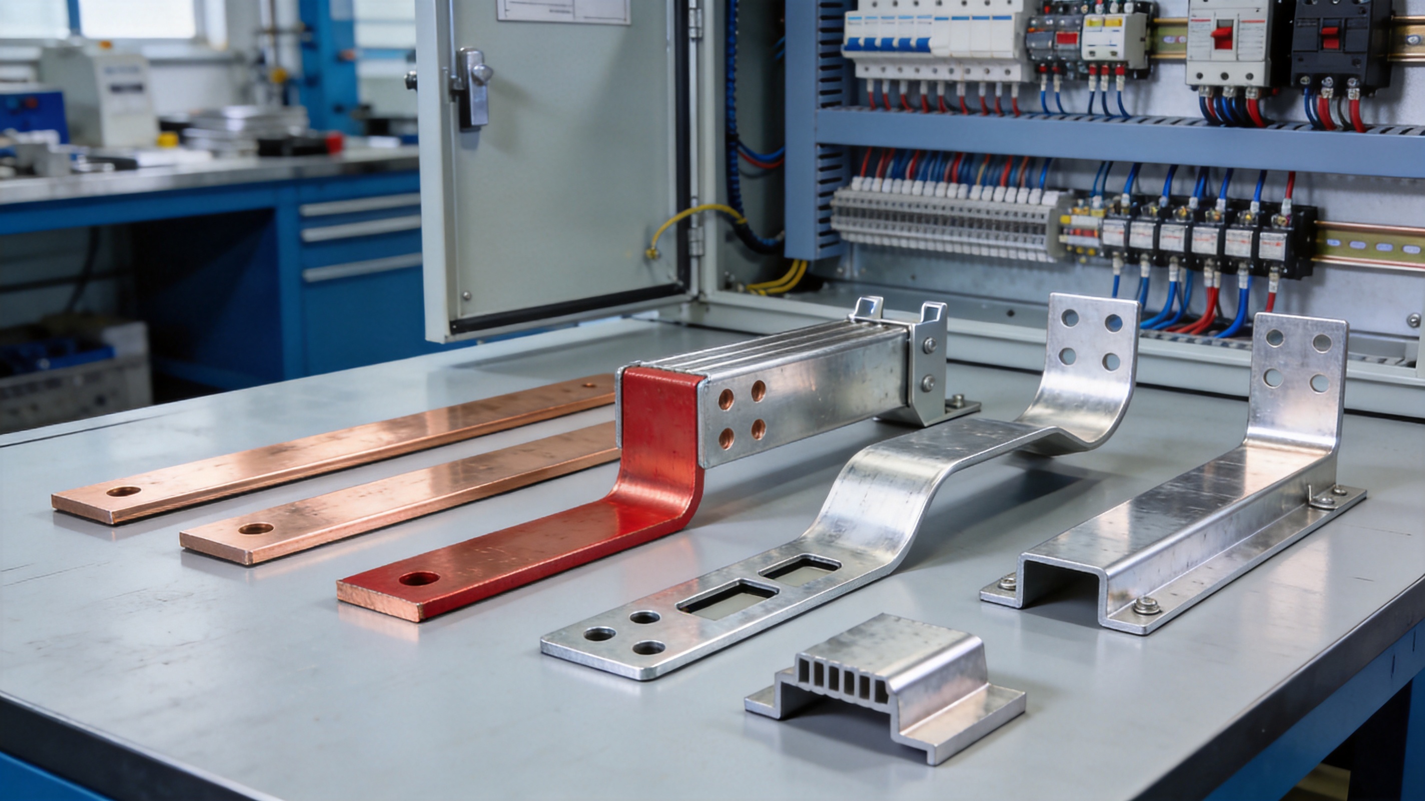
The main advantage of a tin-plated copper busbar over an untreated copper busbar is surface protection. Bare copper provides excellent conductivity, but its exposed surface can oxidize over time. In applications involving humidity, frequent connection and disconnection, storage before assembly, or long operating periods, surface condition becomes an important factor.
Tin plating can help maintain a more stable interface between the busbar and its mating component. It also provides a uniform surface finish that can support consistent assembly. For many electrical systems, this can reduce concerns related to discoloration, surface oxidation, and contact variation.
Tin-plated copper can also provide a practical balance between performance and cost. Silver plating may offer specific advantages in selected high-performance applications, but it can increase material and processing costs. Nickel plating may provide strong surface hardness and environmental resistance, but it may not be the preferred finish for every electrical interface. Tin is widely used because it offers useful electrical contact characteristics and broad manufacturing compatibility.
The correct finish depends on the application. A professional supplier should not promote one coating for every situation. Instead, it should review current, voltage, temperature, humidity, mating material, assembly method, storage conditions, and expected service life before confirming the final specification.
Comparison Factor |
Untreated Copper Busbar |
Tin-Plated Copper Busbar |
Electrical Conductivity |
Very high through the copper substrate |
High, with a protected conductive contact surface |
Surface Oxidation |
More exposed to natural oxidation and discoloration |
Tin layer helps protect the copper surface |
Connection Stability |
Depends strongly on surface condition and maintenance |
Can support more consistent contact when correctly specified |
Environmental Durability |
May require additional protection in humid environments |
Improved surface protection for many industrial applications |
Application Flexibility |
Suitable where cost and high conductivity are primary concerns |
Suitable for electrical interfaces requiring conductivity and surface protection |
Customization |
Can be stamped, bent, and machined |
Can be customized with plating, forming, holes, and integrated features |
Cables remain useful for flexible routing and difficult-to-reach locations, but a busbar can provide clear advantages in structured power distribution systems. A rigid busbar occupies a defined space and can be designed to connect multiple points through one formed component. This may reduce cable count, terminal count, and the amount of manual routing required during assembly.
Busbars can also improve repeatability. A cable assembly may require cutting, stripping, crimping, labeling, routing, and tightening. A stamped busbar arrives with its geometry already defined. The assembler only needs to position and secure it according to the product design. This can help reduce variation between units and support higher production efficiency.
Another advantage is space utilization. A customized busbar can follow the internal shape of a cabinet, module, or electrical enclosure. Bends and formed sections allow the conductor to pass around components while preserving the required clearance. This can be valuable in compact battery modules, relay products, and vehicle power systems.
However, busbars are not a universal replacement for cables. They are best suited to applications where a rigid conductive structure is practical. Vibration, movement, thermal expansion, service access, and insulation requirements must be evaluated before selecting a busbar solution.
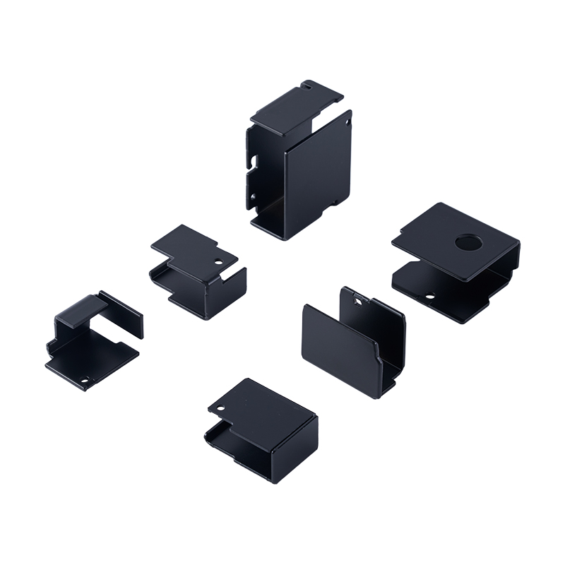
One of the most important benefits of working with a specialized stamping manufacturer is the ability to integrate several functions into one metal component. A tin-plated copper busbar can be customized with dimensions, thickness, hole positions, slots, bends, contact tabs, embossed areas, threaded holes, and other features.
The design process normally begins with a two-dimensional drawing, a three-dimensional model, a physical sample, or a written specification. Engineering staff review the drawing for material suitability, bend radii, hole-to-edge distances, forming direction, plating requirements, and inspection points. If the design is not suitable for stamping or forming, the supplier may recommend adjustments before tooling begins.
Precision tooling is especially important for parts that must fit into compact relay or connector assemblies. A well-designed die can control cutting, punching, forming, and progressive operations with high repeatability. Tooling quality affects edge condition, dimensional consistency, production speed, and long-term manufacturing cost.
The stated dimensional tolerance for customized products can reach ±0.01 mm in suitable features and processes. Actual achievable tolerance depends on material thickness, product geometry, process sequence, tooling design, measurement method, and the specific dimension being controlled. Engineering confirmation should always be completed before this tolerance is adopted as a final product requirement.
OEM and ODM customers can provide CAD, DWG, IGS, STP, three-dimensional files, or samples. This allows the manufacturer to support both new product development and replacement sourcing. Prototype sampling can be used to verify fit, assembly, electrical performance, and production feasibility before mass manufacturing.
Manufacturing begins with material verification. The copper or copper alloy must match the approved specification for thickness, width, hardness, conductivity, and mechanical properties. Incoming material inspection helps prevent variation from entering later processes.
Material preparation may include slitting, leveling, cutting, cleaning, and identification. Proper flatness is important because uneven strip material can affect feeding, punching, forming, and final assembly. Material traceability also supports quality records and customer documentation.
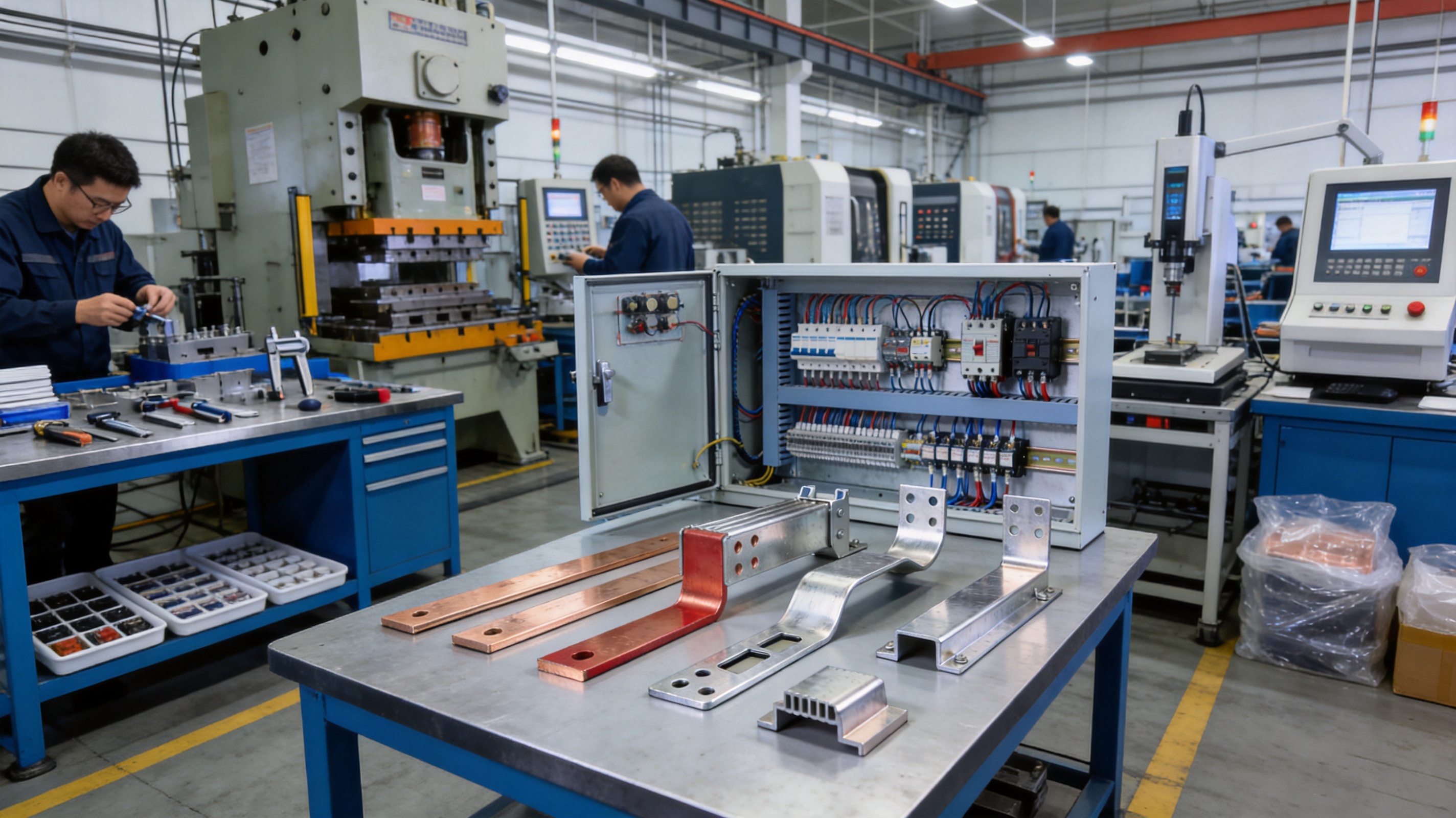
Stamping is suitable for producing repeatable shapes at medium and high volumes. Depending on the design, a progressive die may perform blanking, punching, notching, bending, and forming in a controlled sequence. This reduces manual handling and helps maintain consistent part-to-part geometry.
The die must be designed around the material, thickness, bend requirements, hole pattern, and production quantity. Cutting clearance affects burrs and edge quality. Forming stations must account for springback and the mechanical properties of the selected copper alloy. Proper process planning can reduce secondary correction and improve production efficiency.
Some components require localized depth, raised sections, or three-dimensional forms. Deep drawing and specialized forming methods can create these features when the material and geometry are suitable. The process must control thinning, cracking, wrinkling, and dimensional change.
For busbar products, formed sections may be used for positioning, clearance, contact pressure, or structural reinforcement. A design review is necessary to verify that the forming operation does not create stress concentrations or interfere with the final plating condition.
Laser cutting is useful for prototypes, low-volume orders, complex profiles, and designs that may change during product development. It can reduce the initial tooling requirement and allow quick evaluation of a new geometry.
Once the design becomes stable and the production volume increases, stamping may offer better cycle time and unit economics. A supplier that supports both laser cutting and stamping can recommend the most suitable process for each project stage.
CNC punching can produce accurate holes, slots, and profiles based on programmed data. Threading and tapping add mechanical fastening features where the busbar must connect directly to screws or other hardware. These operations require careful control of hole size, thread quality, burr removal, and alignment.
When a customer’s assembly requires multiple fasteners, accurate hole positioning is critical. Poor alignment can increase installation time or place stress on the busbar and mating components. Coordinate inspection and fixture-based verification can help control these risks.
Bending creates the three-dimensional shape needed to fit the final enclosure or module. The manufacturing team must consider bend radius, material hardness, springback, grain direction where relevant, and the position of plated or contact surfaces.
Additional operations may include welding, riveting, deburring, polishing, or mechanical joining. Each secondary operation should be defined in the product specification because it may affect electrical resistance, coating condition, mechanical strength, or appearance.
Surface treatment is a key stage in the production of a tin-plated copper busbar. Before plating, the copper surface must be clean and properly prepared. Oil, oxide, dust, and processing residue can reduce coating adhesion or create nonuniform areas. Cleaning and pretreatment therefore require controlled procedures.
The tin coating should cover the specified areas consistently. Depending on the customer’s design, certain regions may require full plating while other areas may be masked or treated differently. The supplier must confirm coating thickness, appearance, adhesion, coverage, and any restrictions related to soldering or mechanical contact.
Other surface treatments may be available for different components or project requirements, including polishing, nickel plating, zinc plating, brushing, powder coating, anodizing, paint, sandblasting, acid pickling, and hot-dip galvanizing. Not all treatments are suitable for every copper busbar application. Selection should be based on electrical performance, corrosion requirements, mechanical function, and the final assembly environment.
Surface inspection can include visual examination, coating thickness measurement, adhesion checks, dimensional verification after plating, and electrical performance testing. The inspection plan should reflect the customer’s drawings and quality agreement.
Quality control begins before production. Drawing review, material approval, process planning, tool verification, and first-article inspection help establish the correct manufacturing conditions. The objective is not only to detect defective products but also to prevent process variation.
Dimensional inspection may include length, width, thickness, hole diameter, hole position, bend angle, flatness, and overall profile. Depending on the design, coordinate measuring equipment, optical inspection, gauges, calipers, micrometers, and custom fixtures may be used.
Electrical inspection can include conductivity-related verification, resistance checks, contact performance assessment, or other tests specified by the customer. The test method must correspond to the product and should be agreed before mass production.
Visual inspection is also important. Inspectors check for scratches, cracks, burrs, dents, incomplete plating, discoloration, contamination, deformation, and other conditions that may affect installation or service performance. For plated products, both the conductive surfaces and protected surfaces require attention.
Taoyang provides 100% quality inspection before delivery and can support inspection reports according to customer requirements. Its management system includes ISO 9001 quality management, ISO 14001 environmental management, ISO 45001 occupational health and safety management, and IATF 16949 automotive quality management certifications. Products have also passed relevant RoHS and REACH testing requirements, supporting customers that require controlled material content and environmental compliance.
Zhejiang Taoyang Electronics Co., Ltd. was founded in 2010 and specializes in hardware supporting products and solutions for electrical and electronic products, relays, current transformers, electricity meters, new energy systems, energy storage equipment, and automotive applications. This industry focus gives the company experience with conductive stamped parts that must meet both electrical and mechanical requirements.
The company’s capabilities include mold and tooling design, stamping, deep drawing, laser cutting, bending, CNC punching, threading, welding, tapping, and riveting. These processes allow customers to source multiple stages of production from one manufacturing partner. Consolidating tooling, forming, surface treatment, inspection, and packaging can simplify communication and improve project coordination.
Advanced tooling development is particularly important for customized busbars. The company can create production tooling based on customer drawings, three-dimensional models, or samples. Tooling engineers can analyze forming sequences, material flow, hole positions, and dimensional control before the first production run.
Taoyang also emphasizes in-process quality control and manufacturing capacity. For OEM and ODM customers, this combination is valuable because the supplier must support prototype sampling, design changes, trial production, and stable mass production. A supplier that only offers basic cutting may not be able to manage the complete transition from sample to volume production.
The company serves more than 100 leading customers in China and overseas and has been recognized as a technology-based small and medium-sized enterprise and a National High-tech Enterprise. Its product fields include new energy, energy storage, automotive parts, electronics, and electrical equipment.
Continuous innovation is part of the company’s operating approach. Innovation may involve tooling structure, production efficiency, inspection methods, process management, material utilization, and product development. For customers, this can translate into more practical solutions for difficult shapes, compact assemblies, and demanding production schedules.
A complete technical specification should begin with the electrical requirements. The customer should provide nominal current, peak current, operating voltage, expected temperature range, duty cycle, allowable temperature rise, and installation environment. These details help determine the suitable material, cross-sectional area, plating, and connection structure.
Mechanical information is equally important. The drawing should identify overall dimensions, thickness, hole patterns, bend angles, bend radii, mounting points, flatness requirements, and critical tolerances. It should also identify areas that must remain free from burrs, plating, paint, or other surface conditions.
The customer should specify the required copper or copper alloy. Pure copper and T2Y2 are common conductive options, while beryllium copper and phosphorus bronze may be selected for special mechanical or spring characteristics. Material substitution should not be made without engineering approval because it can change conductivity, hardness, forming behavior, and contact performance.
Plating information should include the coating material, required areas, thickness, appearance, masking requirements, and test expectations. If the busbar will be used in a humid, corrosive, high-temperature, or high-vibration environment, these conditions should be disclosed during quotation and engineering review.
Documentation requirements may include material certificates, dimensional reports, plating reports, inspection records, RoHS or REACH declarations, first-article reports, and packaging specifications. Clear documentation helps align the manufacturer’s process with the customer’s quality system.
Specification Area |
Information to Confirm |
Base Material |
Pure copper, T2Y2, beryllium copper, phosphorus bronze, or approved alternative |
Electrical Requirements |
Current, voltage, duty cycle, resistance, temperature rise, and operating environment |
Dimensions |
Length, width, thickness, bend dimensions, hole positions, and critical tolerances |
Processing |
Stamping, laser cutting, bending, CNC punching, threading, welding, tapping, or riveting |
Surface Treatment |
Tin plating and any required cleaning, masking, polishing, or additional treatment |
Drawing Format |
CAD, DWG, 3D, IGS, STP, or physical sample |
Inspection |
Dimensional checks, visual inspection, electrical verification, coating inspection, and reports |
Packaging |
Protective packaging, labeling, quantity per package, and export requirements |
Prototype sampling allows the customer to evaluate a busbar before committing to full-scale production. During this stage, the sample can be checked for fit, hole alignment, bend accuracy, contact performance, assembly sequence, and interference with neighboring parts.
For simple low-volume parts, laser cutting and limited tooling may be appropriate. For higher volumes, progressive stamping or dedicated tooling may improve productivity and consistency. The correct choice depends on annual demand, material thickness, geometry, tolerance, and expected product life.
After sample approval, process documentation and inspection standards should be finalized. The supplier can then move to trial production and mass production with defined material, tooling, machine settings, inspection points, and packaging procedures.
Taoyang supports prototype sampling and mass production. Regular orders generally require a lead time of approximately six to eight weeks, while customized products generally require five to nine weeks after payment, depending on project complexity. The final schedule should be confirmed according to tooling requirements, material availability, plating specifications, sample approval, and order quantity.
Tin-plated busbars should be packaged to prevent scratching, bending, contamination, and contact damage during storage and transportation. Packaging may include separators, protective film, trays, bags, cartons, or customer-specified returnable containers. The appropriate method depends on the product shape, plating condition, and shipping distance.
Labeling should identify the part number, revision, quantity, lot number, production date, and other information required by the customer. Clear labels help prevent mixing between similar busbar models, especially when multiple thicknesses or hole patterns are used in one project.
Taoyang offers customized packaging solutions and supports EXW or CIF trade terms. Stock samples may be available, while OEM and ODM samples can be produced from drawings or physical samples. Payment terms include full payment for sample orders and, for bulk orders, a typical structure of 50 percent advance payment with the balance due before delivery, subject to order confirmation.
Electrical equipment manufacturers increasingly require suppliers to control restricted substances, manufacturing waste, energy use, and process emissions. Tin-plated copper busbars should be produced with materials and surface treatments that meet the customer’s environmental requirements.
RoHS and REACH-related documentation may be requested for products used in electronics, automotive systems, energy storage, and electrical equipment. The exact compliance obligations depend on the destination market and the customer’s product category. Suppliers should provide applicable declarations or test documents when required.
Environmental management also includes responsible handling of plating chemicals, metal scrap, wastewater, packaging materials, and production residues. An ISO 14001 environmental management system provides a structured framework for managing these issues, although customers should confirm the specific documents and controls required for their project.
Choosing a specialized manufacturer can reduce technical risk. A busbar supplier with experience in stamping and electrical hardware understands that the product must satisfy both dimensional and conductive requirements. The supplier can consider how material selection, tooling, forming, plating, and assembly interact.
A specialized manufacturer can also provide earlier engineering feedback. If a hole is too close to an edge, a bend radius is too small, a plating area is difficult to control, or a tolerance is unnecessarily tight, the supplier can identify the issue before production. Early design-for-manufacturing review may reduce tooling changes and avoid delays.
Another advantage is process integration. When mold design, stamping, secondary processing, plating, inspection, and packaging are coordinated by one supplier, responsibility is clearer. This can simplify communication and improve traceability compared with managing several independent vendors.
Taoyang’s experience in relays, electrical products, current transformers, new energy, energy storage, and automotive applications supports this integrated approach. The company’s certifications, testing support, tooling capability, production experience, and after-sales service are designed to support long-term OEM and ODM relationships.
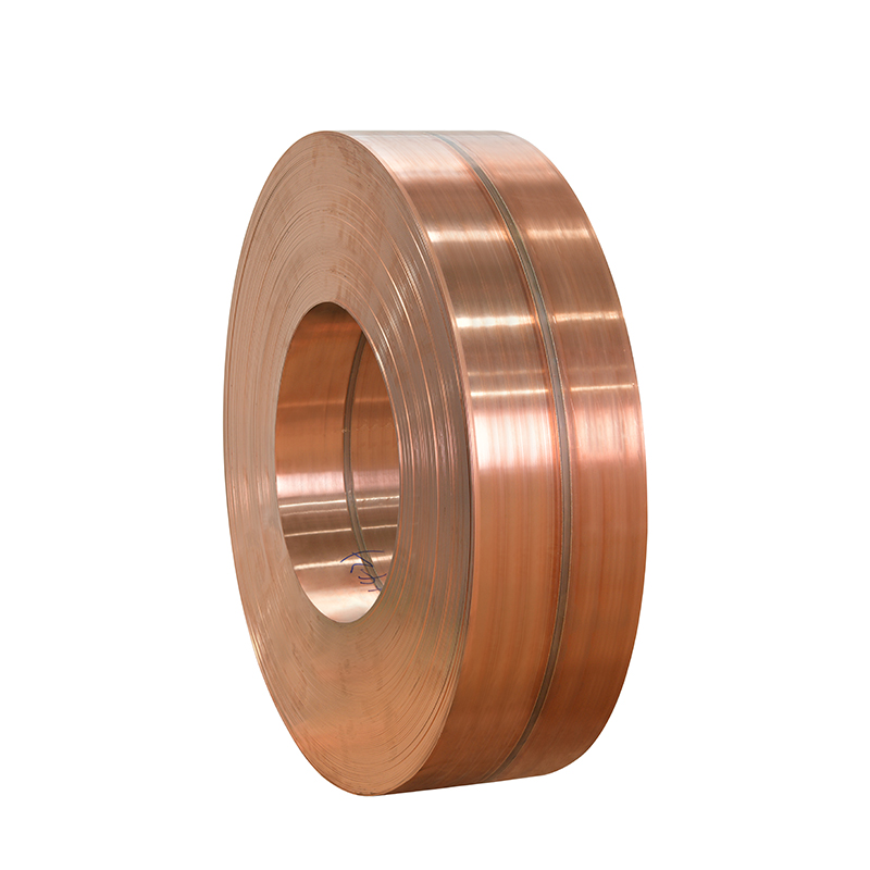
Available materials include pure copper, T2Y2, beryllium copper, and phosphorus bronze, depending on the required conductivity, strength, spring behavior, forming performance, and application environment. The final material should be confirmed against the customer’s drawing and technical requirements.
Yes. Customized busbars can be produced from CAD drawings, DWG files, three-dimensional models, IGS files, STP files, or physical samples. The manufacturer can review the design, develop tooling, produce prototypes, and support mass production after approval.
The stated tolerance for suitable customized features can reach ±0.01 mm. Actual performance depends on material, geometry, process, tooling, and measurement conditions. Critical dimensions should be reviewed and confirmed during engineering development.
Available processes include stamping, deep drawing, laser cutting, bending, CNC punching, threading, welding, tapping, and riveting. The process combination is selected according to product geometry, volume, tolerance, material, and assembly requirements.
Tin plating helps protect the copper surface from oxidation and can support more stable electrical contact. It is suitable for many power distribution, control, relay, battery, and industrial electrical applications. The final coating should be selected according to the operating environment and connection design.
It can be suitable for battery modules, battery packs, power distribution units, and related electrical connections when the busbar is correctly designed for current capacity, temperature rise, insulation clearance, vibration, and fastening requirements. Application-specific testing and engineering approval remain necessary.
Yes. Packaging can be customized according to product shape, plating protection requirements, shipping method, quantity, labeling, and customer assembly needs. Separators and protective materials may be used to reduce scratching and deformation.
Quality control can include material verification, dimensional inspection, visual inspection, hole and bend checks, plating inspection, electrical performance verification, and final 100 percent inspection before delivery. Inspection reports can be supplied according to customer requirements.
Regular orders typically require six to eight weeks. Customized products generally require five to nine weeks after payment, depending on product complexity, tooling, material availability, surface treatment, sample approval, and order quantity.
An inquiry should include the product drawing or sample, material, thickness, dimensions, plating requirements, quantity, tolerance, application, inspection requirements, packaging requirements, and delivery destination. Providing complete information helps the manufacturer prepare a more accurate quotation and schedule.
Tin-plated copper busbars combine the high conductivity and formability of copper with the surface protection of tin. They provide a practical solution for power distribution, industrial control panels, switchgear, battery energy storage, new energy vehicles, relays, connectors, and other electrical systems that require dependable current transmission.
The most important benefits include stable conductivity, improved oxidation resistance, reliable connection surfaces, compact structural integration, and compatibility with customized manufacturing. Compared with untreated copper or complex cable assemblies, tin-plated busbars can offer improved connection consistency, better space utilization, and reduced assembly complexity when correctly designed.
Product performance depends on more than the base material. Tooling quality, stamping accuracy, forming control, plating preparation, inspection, packaging, and application engineering all contribute to the final result. A capable manufacturer must therefore provide a complete process chain from drawing review and prototype development to production, quality verification, and delivery.
Zhejiang Taoyang Electronics Co., Ltd. supports these requirements through expertise in hardware stamping, mold and tooling development, precision processing, surface treatment coordination, quality management, and customized OEM and ODM production. With experience serving electrical, relay, automotive, energy storage, and new energy customers, the company is positioned to support both prototype projects and repeat mass production.
For a customized tin-plated copper busbar project, buyers should provide the relevant drawings, electrical conditions, material preferences, coating requirements, tolerances, inspection standards, and packaging details. Early cooperation between the customer’s engineering team and the manufacturer can produce a more efficient design, a more stable process, and a more reliable finished component.
1. Copper Development Association, Copper Busbar Design and Electrical Conductor Engineering Principles.
2. International Electrotechnical Commission, Low-Voltage Switchgear and Controlgear Assembly Standards.
3. International Organization for Standardization, ISO 9001 Quality Management Systems.
4. International Organization for Standardization, ISO 14001 Environmental Management Systems.
5. International Organization for Standardization, ISO 45001 Occupational Health and Safety Management Systems.
6. International Automotive Task Force, IATF 16949 Automotive Quality Management System Requirements.
7. Restriction of Hazardous Substances Directive, Requirements for Electrical and Electronic Equipment.
8. Registration, Evaluation, Authorisation and Restriction of Chemicals, General Compliance Principles for Industrial Materials.
9. Metal Forming and Precision Stamping Engineering Practice, Material Selection, Tooling Design, and Process Control.
10. Electrical Contact Engineering Principles, Surface Protection, Contact Resistance, and Connection Reliability.





 English
 русский
 Français
 日本語
 Español
 Deutsch
 عربى
 Indonesia
 +86-18257772883