
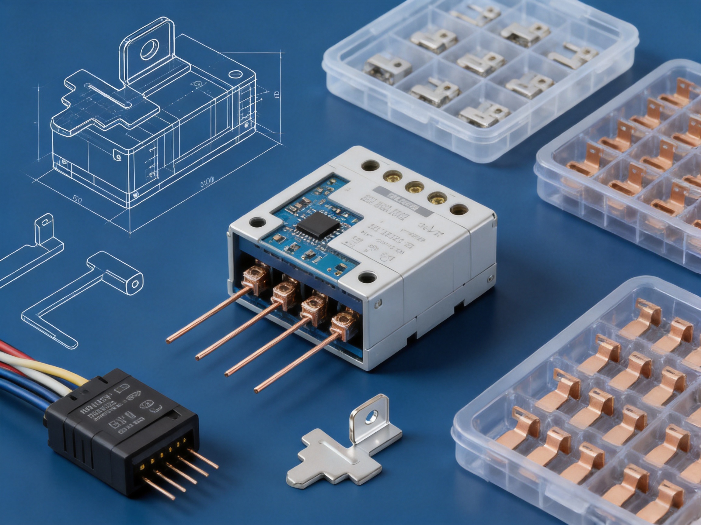
Copper conductive pins are small components with a critical role in electrical and electronic assemblies. Although their dimensions may be modest, their performance directly influences current transmission, contact stability, assembly efficiency, and the service life of the finished product. In relays, connectors, PCB modules, wiring harnesses, household appliance controllers, and energy-related equipment, a conductive pin must provide dependable electrical contact while also tolerating repeated insertion, vibration, bending, heat, and long-term operation.
The Copper Conductive Pin is designed as a precision electrical connection component for manufacturers that require consistent dimensions, stable conductivity, and reliable mechanical performance. It is produced from selected copper and copper-alloy materials through precision stamping and surface treatment. Depending on the application, available materials include pure copper, beryllium copper, phosphor bronze, and T2Y2 copper alloy. These material options allow engineers to balance conductivity, spring characteristics, strength, corrosion resistance, and production cost.
For relay and connector manufacturers, the value of a conductive pin is not determined by conductivity alone. A pin that transmits current efficiently but varies excessively in length, diameter, flatness, or contact geometry can create assembly problems and unstable contact resistance. The manufacturing process must therefore control material quality, tooling accuracy, stamping conditions, surface finish, inspection, and packaging. Zhejiang Taoyang Electronics Co., Ltd. combines these production capabilities to supply customized conductive pins for electronic, electrical, automotive, new energy, and energy storage applications.
This article explains the construction, benefits, applications, customization options, production process, quality controls, and purchasing considerations associated with precision copper conductive pins.
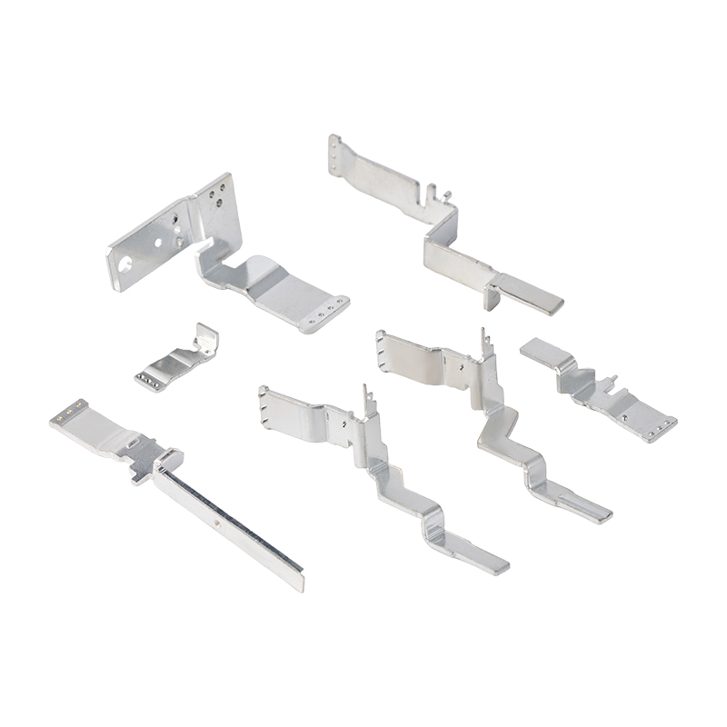
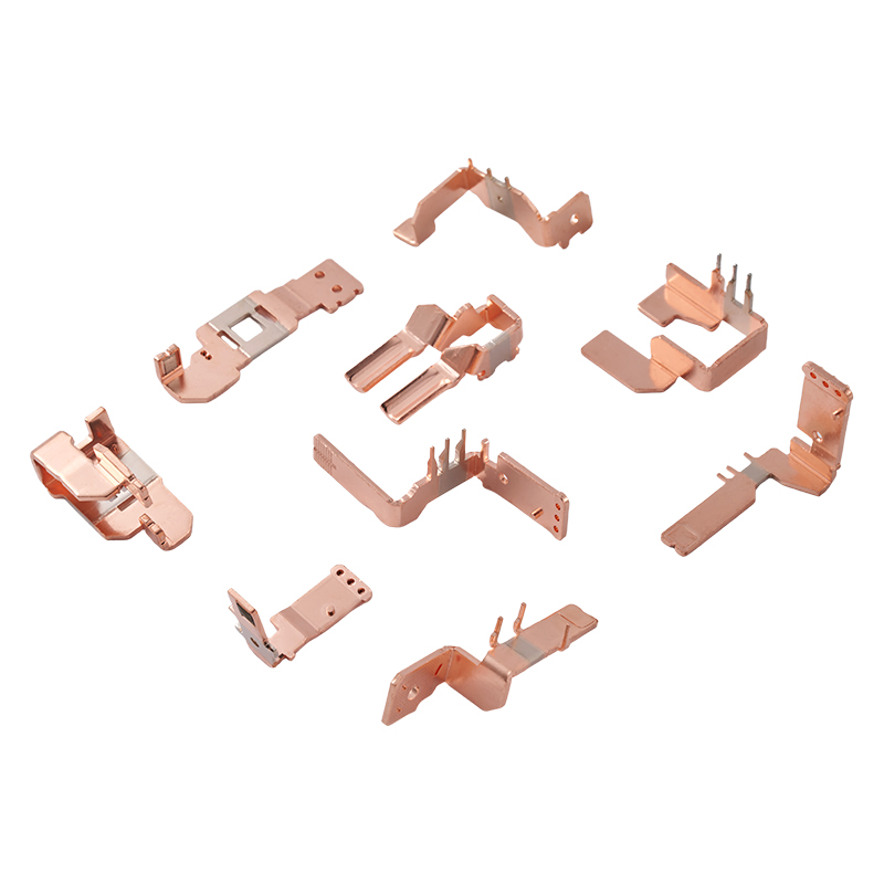
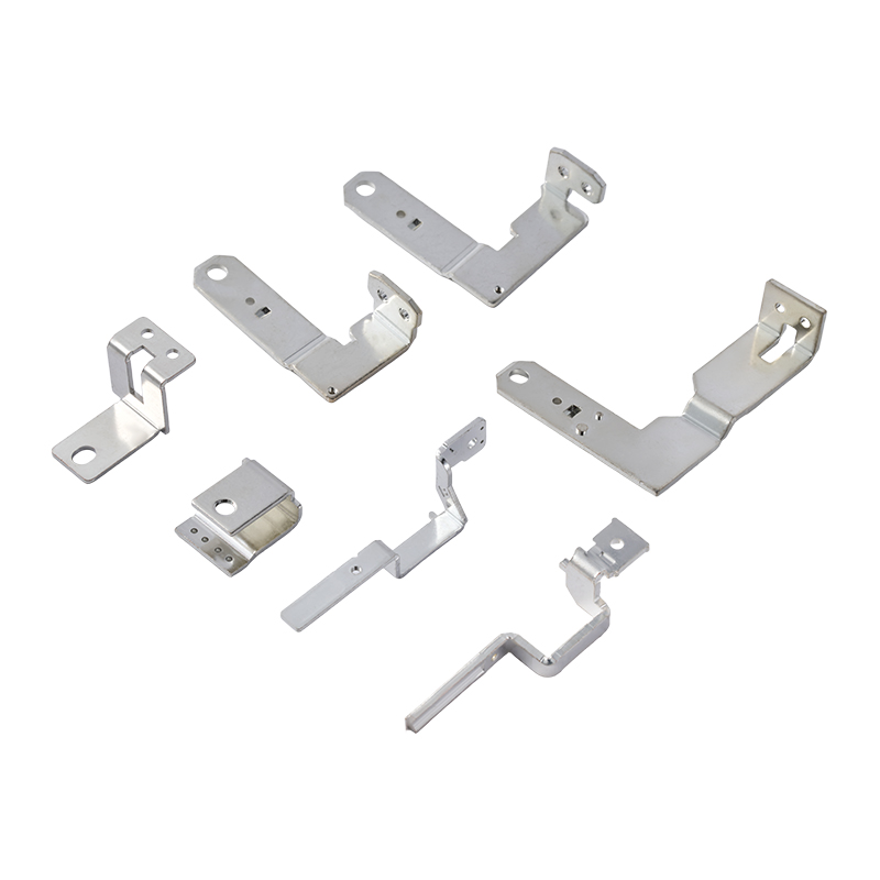
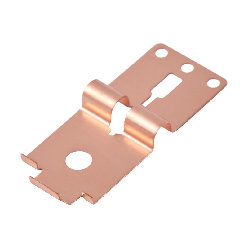
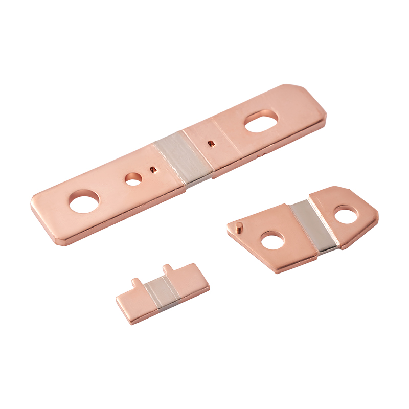
A Copper Conductive Pin is a compact metal connection part manufactured primarily from copper or a copper alloy. It is used to create a conductive path between electrical components, terminals, contact systems, circuit boards, wiring assemblies, or relay structures. Depending on the product design, the pin may be straight, stepped, formed, bent, riveted, threaded, or integrated into a stamped contact assembly.
The basic function is simple: the pin transfers electrical current from one connection point to another. However, its engineering requirements can be complex. It may need to fit within a confined housing, maintain a defined contact force, pass through a PCB or connector body, resist movement during assembly, and preserve low and stable contact resistance throughout the product’s service life.
Precision conductive pins are generally produced from materials with high electrical conductivity and favorable forming characteristics. Pure copper is suitable where maximum conductivity is a primary requirement. Beryllium copper can offer a useful combination of conductivity, strength, and elasticity. Phosphor bronze provides good spring properties, fatigue resistance, and corrosion performance. T2Y2 copper alloy can be selected for applications requiring a balance between electrical and mechanical properties.
After forming, the pin may receive a surface coating or finishing treatment. Plating and other treatments can improve solderability, contact stability, wear resistance, corrosion resistance, and compatibility with mating components. The appropriate treatment depends on the operating environment, current level, mating frequency, temperature, and requirements of the complete electrical assembly.
Electrical connection components work at the interface between mechanical and electrical systems. Their dimensions determine how they fit, while their material and surface determine how they conduct. A design may fail if either side is inadequately controlled.
Dimensional variation can create several problems. A pin that is too short may not make sufficient contact. A pin that is too long may interfere with the housing or produce excessive mechanical stress. Variation in diameter or formed geometry can cause loose fitting, difficult insertion, poor alignment, or damage to mating parts. In automated assembly, even small inconsistencies can increase machine stoppages and rejection rates.
Surface condition is equally important. Oxidation, burrs, contamination, uneven plating, or rough contact areas can increase contact resistance. In relay applications, unstable contact resistance may result in heat generation, signal interruption, arcing risk, or inconsistent switching performance. For low-voltage electronic systems, even a small change in connection quality can affect signal integrity and operational reliability.
Mechanical strength also influences product life. Conductive pins are often inserted, bent, crimped, welded, riveted, or assembled into housings. During service, they may experience vibration, thermal cycling, shock, and repeated mating. A strong and accurately formed pin is less likely to deform, loosen, crack, or lose alignment.
For these reasons, precision conductive pins should be evaluated as engineered components rather than simple pieces of copper. Material selection, tooling design, forming control, surface treatment, inspection, and traceability all contribute to the quality of the final connection.
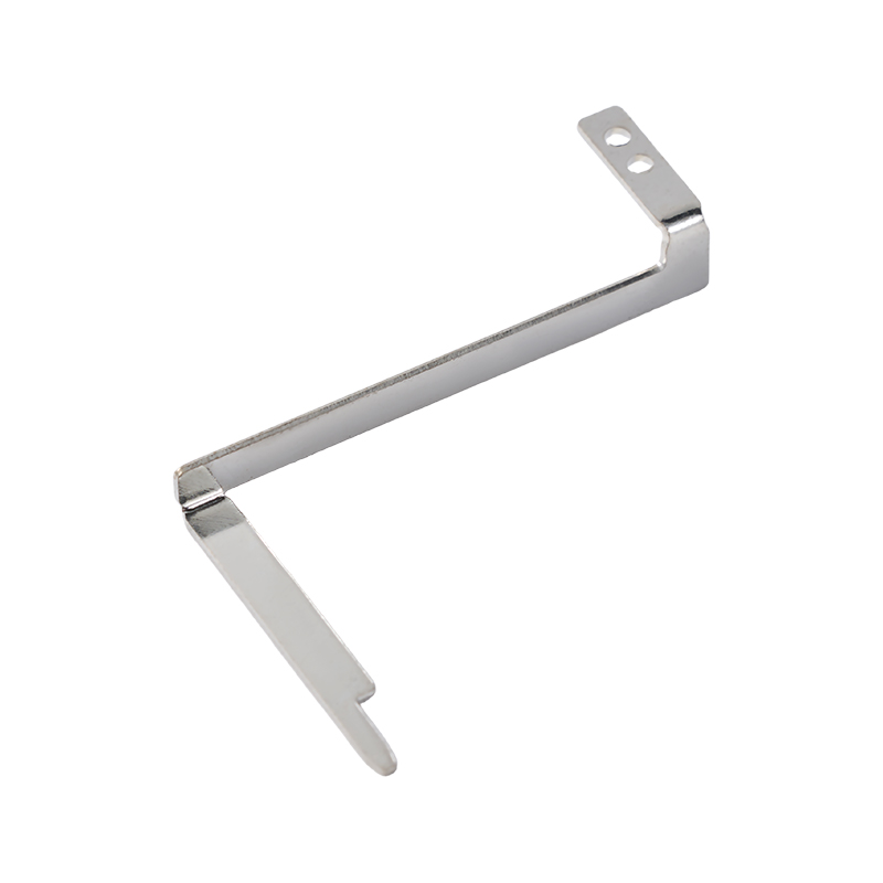
Copper Conductive Pin
Copper is widely used for electrical connection components because it provides excellent conductivity in a compact form. A copper conductive pin can transfer current efficiently while occupying limited space inside a relay, connector, control unit, or wiring assembly. This supports compact product design and helps reduce unnecessary electrical losses.
Material selection can be adapted to the electrical and mechanical requirements of the application. Pure copper may be selected for high-conductivity applications. Where the pin must also provide greater strength, spring action, or resistance to repeated loading, a copper alloy may be more suitable. This flexibility enables the component to be matched to the actual performance requirements instead of relying on one material for every application.
Stable contact performance depends on the combined effect of contact geometry, material, surface treatment, dimensional accuracy, and assembly fit. The precision manufacturing process helps maintain consistent pin dimensions and contact areas. Surface coating treatment can further support stable contact resistance and protect the base material from environmental influences.
For relay and connector applications, stable contact performance is especially important because the connection may be opened and closed repeatedly or exposed to vibration. A well-controlled conductive pin helps maintain predictable electrical behavior during the operating life of the assembly.
The integrated stamped structure provides good resistance to bending and supports repeated assembly operations. Properly designed stamping features can improve rigidity, positioning, and retention within the finished component. The pin can also be configured for different joining methods, including welding, riveting, insertion, crimping, or soldering.
Mechanical durability is valuable in automotive electronics, energy storage equipment, industrial controllers, and household appliances, where components may experience vibration, movement, temperature changes, and repeated maintenance or assembly activities.
The product can be manufactured to a dimensional tolerance of approximately ±0.01 mm for applicable features and designs. This level of control supports accurate fitting in compact electronic assemblies and improves repeatability across mass-produced batches.
Tolerance requirements should always be confirmed against the actual drawing and geometry. Different dimensions may have different practical tolerances depending on material thickness, forming method, feature shape, and production volume. During technical review, the manufacturer can evaluate the drawing or sample and recommend a suitable manufacturing process.
Modern electronic products continue to become smaller and more integrated. Conductive pins must often fit inside narrow housings, dense PCB layouts, miniature relays, or multi-contact connectors. Precision stamping allows the manufacturer to create compact profiles, formed sections, and integrated features while maintaining repeatable production.
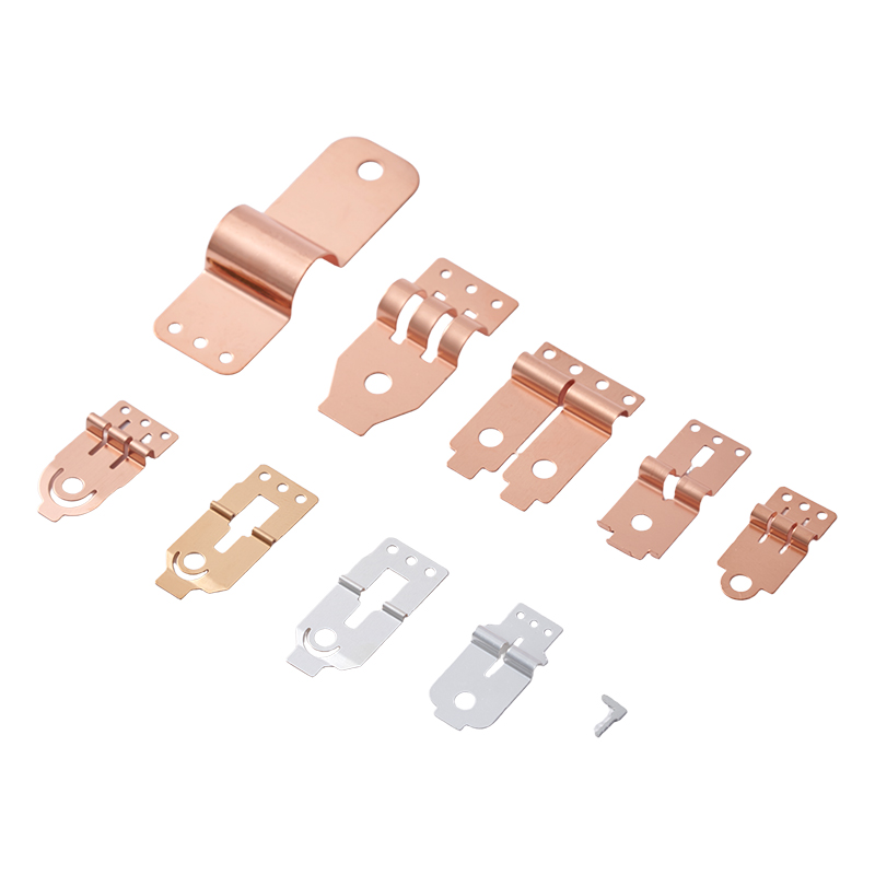
Customized pin lengths, widths, thicknesses, bends, holes, steps, and contact structures can be developed according to customer drawings or physical samples. This helps engineers optimize the connection component for the available installation space.
Consistent dimensions and controlled surface condition are essential for automated assembly. Feeding systems, insertion machines, welding equipment, and inspection stations all depend on predictable component geometry. Stable batch production can help reduce machine adjustments, material jams, misalignment, and manual rework.
When combined with suitable packaging, precision conductive pins can be supplied in a format appropriate for the customer’s production line. Packaging may be customized for bulk orders to support protection, counting, storage, and efficient material handling.
Conductive pins from different suppliers may appear similar, but their production quality can differ significantly. The main distinction is often not the visible shape but the consistency of the material, forming process, plating, inspection, and batch control.
Lower-precision pins may be produced with limited tooling control or inconsistent raw material. They can show variation in length, burr size, flatness, hole position, or forming angle. These differences may not be obvious during a basic visual inspection, but they can become apparent during high-speed assembly or long-term operation.
Precision copper conductive pins offer several potential advantages over generic alternatives:
These advantages do not mean that every application requires the highest possible tolerance or the most complex coating. Instead, the appropriate solution should be selected according to performance requirements, annual demand, assembly method, environmental conditions, and total cost. An experienced manufacturer can help identify the specifications that provide reliable function without unnecessary processing.
Compared with off-the-shelf pins, a customized conductive pin can also reduce the need for additional assembly parts, manual forming, or secondary modification. An integrated stamped design may combine several features into one component, simplifying the customer’s assembly process and reducing potential failure points.
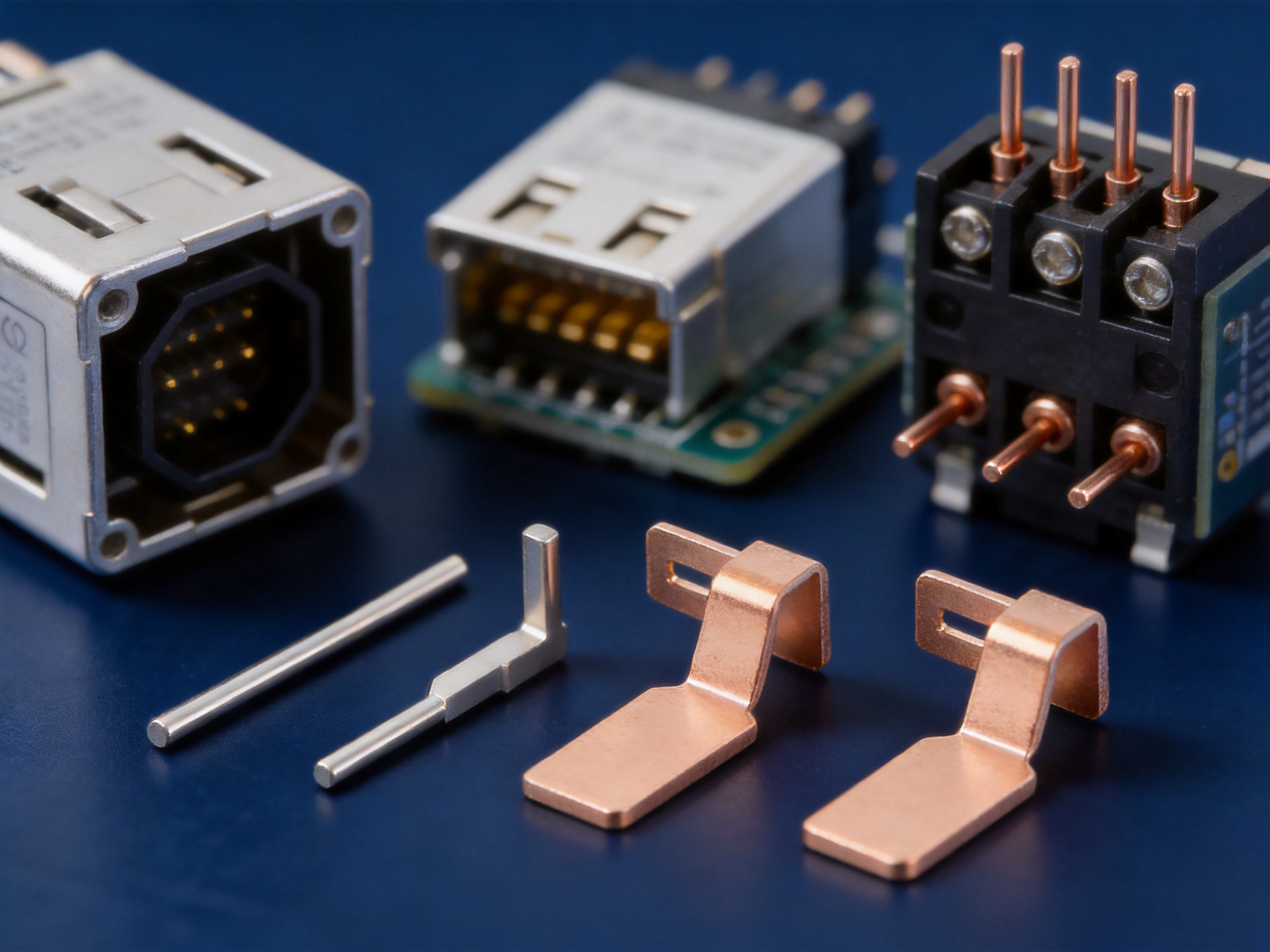
Relays depend on reliable electrical and mechanical contact. Copper conductive pins can be used as connection terminals, internal conductive elements, or supporting contact components. Their dimensions and surface finish can be adapted to the relay housing, contact system, coil assembly, or PCB layout.
Relay manufacturers generally require stable insertion, accurate positioning, suitable current-carrying capacity, and resistance to repeated switching conditions. Material and plating selection should be made according to the relay’s current, voltage, switching frequency, temperature, and environmental requirements.
In connectors, pins establish detachable or semi-permanent electrical connections between cables, PCBs, modules, and equipment. Conductive pins can be produced in straight or formed configurations and may be designed for insertion, crimping, soldering, riveting, or other joining methods.
Connector applications often place strong emphasis on mating accuracy, contact force, retention, corrosion resistance, and wear resistance. A customized pin can be developed to match the connector’s housing, pitch, locking structure, and installation method.
PCB modules use connection pins to link circuit boards with terminals, relays, sensors, control systems, and external wiring. The pin must be compatible with the board hole, soldering process, insertion direction, and component layout.
Precision production helps maintain the position and straightness needed for efficient PCB insertion. Surface treatment may be selected to support solderability or improve the reliability of the mating interface.
New energy equipment includes electric vehicle systems, charging equipment, battery systems, power conversion units, and related control assemblies. These products require dependable current transmission and robust mechanical connections.
Conductive pins used in new energy wiring harnesses may need to withstand vibration, thermal cycling, compact installation spaces, and demanding electrical loads. Material selection, cross-sectional design, plating, and joining method should be evaluated as part of the complete harness or terminal system.
Household appliance controllers use compact terminals and conductive parts in power control boards, motor systems, switching assemblies, sensors, and user-interface circuits. The component must support efficient assembly and stable operation in a cost-sensitive, high-volume production environment.
Precision stamping and automated inspection are useful for maintaining consistent batch quality. Depending on the appliance and circuit design, the pin may be supplied with customized dimensions, bends, holes, or surface treatment.
Electronic control systems in industrial equipment, automotive products, energy devices, and electrical machinery depend on stable interconnections. Conductive pins can be integrated into control modules, terminal assemblies, signal interfaces, and power distribution structures.
The final specification should consider electrical load, signal characteristics, environmental exposure, installation method, and expected service life. A manufacturer with multiple forming and finishing capabilities can help adapt the pin to the system design.
Pure copper is commonly selected when electrical conductivity is the primary requirement. It can provide efficient current transmission and is suitable for many terminals, conductive links, and connection parts. Its forming behavior and strength should be considered when the pin includes narrow sections, repeated bends, or spring functions.
Beryllium copper can provide a useful combination of conductivity, strength, elasticity, and fatigue resistance. It is often considered for contact components that require mechanical resilience or repeated deflection. The precise grade and processing conditions should be confirmed according to the application and applicable compliance requirements.
Phosphor bronze offers good spring performance, wear resistance, and corrosion resistance. It can be suitable for contact and connector components that experience repeated insertion or mechanical movement. Its electrical conductivity is lower than pure copper, but its mechanical properties may provide an advantage in demanding contact structures.
T2Y2 copper alloy can be selected where the design requires a balance of conductivity and mechanical characteristics. The suitability of this material depends on the required thickness, forming geometry, heat treatment, surface finish, and operating environment.
Material choice should be confirmed through a technical review rather than based solely on a material name. The manufacturer can assess the customer’s drawing, current requirements, contact force, forming complexity, and environmental conditions before recommending a practical material.
Production begins with a review of the customer’s drawing, sample, or technical specification. The review considers material, thickness, dimensions, tolerance, forming sequence, surface finish, inspection requirements, and expected production volume.
Drawing files can be supplied in 3D, CAD, DWG, IGS, or STP formats. A physical sample may also be used as a reference for reverse engineering, provided that the final design requirements are confirmed by the customer.
Tooling accuracy has a direct influence on stamped part quality. The die must be designed to control blanking, bending, piercing, forming, and part progression. For high-volume production, progressive or automated tooling can combine multiple operations into an efficient sequence.
Taoyang emphasizes mold and tooling design as one of its manufacturing strengths. Proper tooling development can improve dimensional consistency, reduce material waste, shorten production cycles, and support stable long-term production.
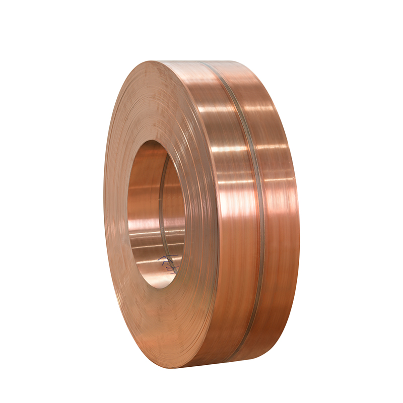
Selected copper or copper-alloy material is prepared according to the required thickness, width, hardness, and surface condition. Material identification and preparation are important because variations in hardness or thickness can affect forming behavior and final dimensions.
For applications with strict electrical or mechanical requirements, material documentation and incoming inspection can help confirm that the supplied material is suitable for production.
Precision stamping forms the basic pin geometry. Depending on the design, the process may include blanking, piercing, bending, forming, embossing, or progressive stamping. Automated stamping equipment supports repeatable production and is suitable for large quantities.
During stamping, process conditions must be controlled to reduce burrs, cracks, distortion, and dimensional variation. Tool wear should also be monitored because worn tooling can gradually affect hole position, edge quality, or formed dimensions.
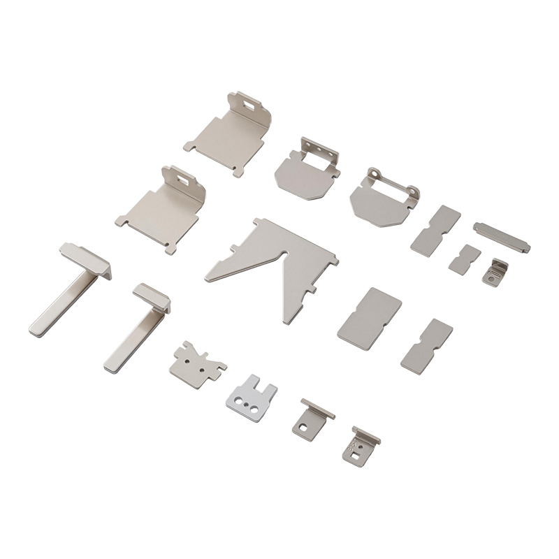
Some conductive pin designs require additional operations after stamping. Available processing capabilities include deep drawing, laser cutting, CNC punching, threading, tapping, bending, welding, and riveting. The appropriate process depends on the component geometry and the required connection method.
Combining multiple processes within one supply chain can simplify procurement and reduce the need for separate subcontractors. It also helps maintain better control of dimensional references and inspection standards throughout production.
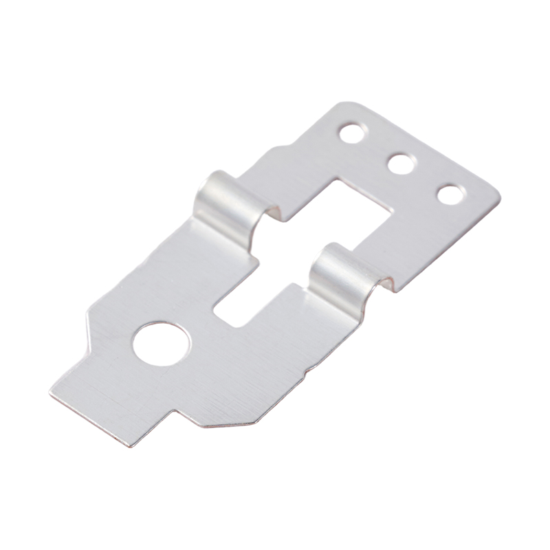
Surface treatment can be used to improve contact performance, appearance, corrosion resistance, solderability, wear resistance, or compatibility with the application environment. Available options include plating, nickel plating, zinc plating, polishing, brushing, sandblasting, painting, powder coating, anodizing, hot-dip galvanizing, acid pickling, and silkscreen printing where applicable.
Not every treatment is suitable for every copper conductive pin. The selection should consider electrical requirements, mating conditions, temperature, humidity, chemical exposure, and cost. Coating thickness and coverage should be defined in the technical specification when they are critical to performance.
Inspection is performed throughout the manufacturing process and before delivery. Dimensional checks help confirm length, width, thickness, hole position, bend angle, and other critical features. Visual inspection can identify burrs, scratches, discoloration, contamination, incomplete forming, or coating defects.
The company provides 100% quality inspection before delivery for applicable products. Inspection records and test reports can support customer quality systems and incoming inspection procedures. Specific inspection items should be agreed during the engineering stage.
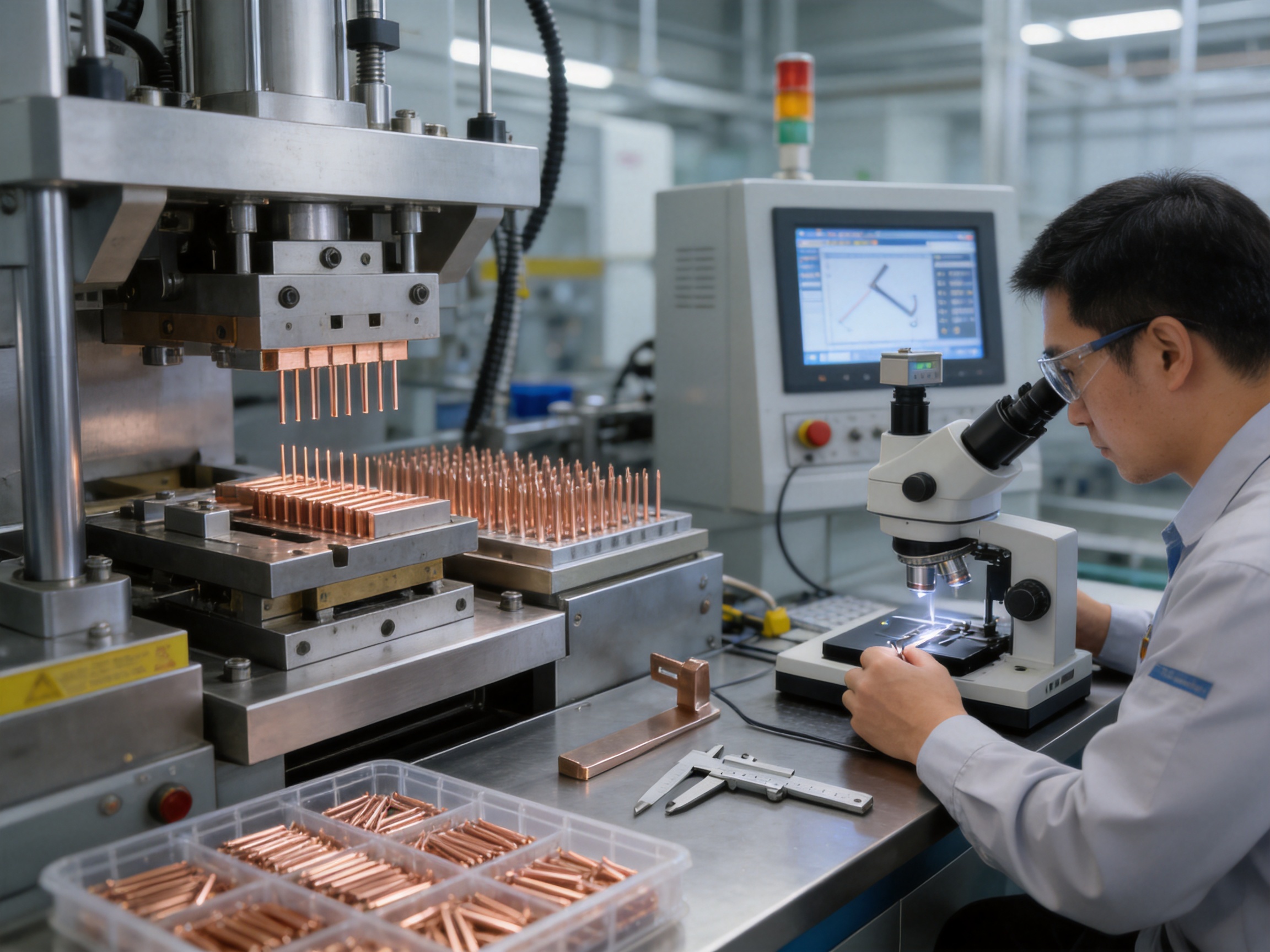
Zhejiang Taoyang Electronics Co., Ltd. was founded in 2010 and specializes in hardware supporting products and solutions for electronic and electrical products, relays, current transformers, electricity meters, new energy systems, energy storage equipment, and automotive applications.
The company operates with an emphasis on product quality and process control. Its management systems include ISO 9001, ISO 45001, ISO 14001, and IATF 16949 certifications. These certifications represent structured approaches to quality management, occupational health and safety, environmental management, and automotive quality requirements.
Products have also passed authoritative compliance tests including RoHS and REACH requirements. Compliance documentation should be confirmed according to the specific material, coating, and product order, especially when the component will be used in regulated markets.
Several manufacturing strengths are relevant to conductive pin production:
Taoyang has been recognized as a Technology-based Small and Medium-sized Enterprise and a National High-tech Enterprise. The company reports that it provides system solutions to more than 100 leading customers in China and overseas. This experience supports the development of customized hardware components for customers with different assembly methods, quality systems, and application requirements.
For buyers, the main benefit of this manufacturing structure is coordination. A conductive pin may require tooling, stamping, coating, inspection, packaging, and technical documentation. Managing these activities through an integrated supplier can reduce communication gaps and make it easier to address design changes or production improvements.
Conductive pins are frequently designed as application-specific parts rather than universal catalog items. Customization can be provided in the following areas:
Customers can select pure copper, beryllium copper, phosphor bronze, T2Y2, or another approved material according to electrical conductivity, mechanical strength, spring requirements, corrosion resistance, and cost.
Pin length, width, thickness, diameter, hole size, bend angle, step height, contact profile, and installation features can be customized. The design should identify critical-to-function dimensions separately from non-critical dimensions to support efficient production and inspection.
Surface treatment can be selected according to contact performance, corrosion resistance, soldering, wear, appearance, and environmental conditions. Coating requirements may include the treatment type, coverage area, thickness, color, and inspection method.
Depending on the design, production may include precision stamping, deep drawing, laser cutting, CNC punching, bending, threading, welding, tapping, or riveting. Selecting the correct process can improve product performance and control production cost.
Customized packaging is available for bulk orders. Packaging may be designed to prevent bending, scratching, oxidation, contamination, or mixing of different specifications. It can also support automated counting and line-side material management.
OEM and ODM samples can be produced based on drawings or physical samples. During the sampling stage, the customer and manufacturer can evaluate fit, assembly, surface condition, dimensional accuracy, and performance before moving to mass production.
Item |
Specification |
Product Name |
Copper Conductive Pin |
Typical Category |
Relay Other Parts and Electrical Connection Components |
Materials |
Pure Copper, Beryllium Copper, Phosphor Bronze, T2Y2 Copper Alloy |
Applicable Tolerance |
Up to approximately ±0.01 mm for applicable features and designs |
Primary Process |
Precision Stamping and Surface Coating |
Additional Processes |
Deep Drawing, Laser Cutting, Bending, CNC Punching, Threading, Welding, Tapping, and Riveting |
Surface Treatments |
Polishing, Plating, Nickel Plating, Zinc Plating, Brushing, Sandblasting, Painting, Powder Coating, Anodizing, Acid Pickling, and Other Applicable Finishes |
Drawing Formats |
3D, CAD, DWG, IGS, and STP |
Inspection |
Full-Process Quality Control and 100% QC Inspection Before Delivery |
Minimum Order Quantity |
1,000 Pieces |
Regular Lead Time |
Approximately 6–8 Weeks |
Custom Product Lead Time |
Approximately 5–9 Weeks After Receipt of Payment, Depending on Design and Tooling |
Trade Terms |
EXW or CIF |
Purchasers should evaluate more than the unit price when selecting a conductive pin supplier. The most economical component is not necessarily the one with the lowest initial price. A part that causes assembly stoppages, high rejection rates, unstable contact, or premature field failures can create a much higher total cost.
Important selection criteria include electrical current, voltage, contact resistance, operating temperature, mating frequency, vibration, corrosion exposure, installation method, and expected service life. The required material and coating should be selected after considering these conditions.
Dimensional requirements should be clearly identified on the drawing. Critical features may include the overall length, contact position, pin straightness, hole location, bend angle, insertion area, and connection interface. If a tolerance of ±0.01 mm is required, the relevant dimension and measurement method should be specified.
Customers should also confirm whether the component will be supplied loose, on tape, in trays, in bags, or in another packaging format. Packaging can influence line efficiency and protect the part during transportation and storage.
Finally, customers should review the supplier’s technical support, tooling capability, inspection system, certifications, compliance documents, sample policy, production capacity, and after-sales service. A supplier able to support both prototype development and stable mass production can be especially valuable for new product programs.
The usual project process begins when the customer provides a drawing, sample, application description, or preliminary specification. The manufacturer reviews the product structure and confirms the material, tolerance, surface treatment, production method, and packaging requirements.
After technical confirmation, tooling may be designed and manufactured. A sample batch is then produced for dimensional, assembly, and functional evaluation. The customer can verify whether the pin fits the housing, PCB, connector, relay, or wiring assembly as intended.
Any design adjustments should be completed before mass production. This stage is an opportunity to improve the bend radius, insertion force, contact area, coating coverage, packaging method, or tolerance allocation. Early cooperation can reduce later tooling changes and production delays.
Once the sample is approved, the manufacturer organizes mass production using the confirmed process parameters and inspection plan. Production orders are monitored through stamping, secondary processing, surface treatment, inspection, and packaging. Final inspection is performed before delivery, and test reports can be provided according to the order requirements.
Stock samples are available for evaluation. OEM and ODM samples can also be produced based on customer drawings or physical samples. The sampling schedule depends on product complexity, tooling requirements, material availability, and surface treatment.
The standard minimum order quantity is 1,000 pieces. Regular orders generally require a lead time of approximately six to eight weeks. Custom products may require approximately five to nine weeks after receipt of payment, depending on the complexity of the design, tooling, surface treatment, and order quantity.
For regular orders, the stated payment arrangement is 100% telegraphic transfer, while sample orders require full payment. For bulk orders, the usual arrangement is 50% telegraphic transfer as an advance payment, with the balance paid before delivery. Final terms should be confirmed in the quotation and sales contract.
Available trade terms include EXW and CIF. Customers should confirm the destination, shipping method, documentation requirements, insurance responsibilities, and import arrangements before placing an order.
For technical quotations, customers should provide the part drawing, material requirement, annual or batch quantity, surface treatment, tolerance, inspection standard, packaging preference, and application information. Supplying complete information at the beginning helps the manufacturer prepare a more accurate quotation and production plan.
Electronic and electrical component supply chains increasingly require attention to environmental compliance, worker safety, and responsible production. Copper and copper alloys can be valuable materials because they support long service life and may be recoverable through established recycling systems at the end of a product’s life.
Surface treatment must be managed carefully because coating processes can affect environmental performance and regulatory compliance. RoHS and REACH-related requirements should be reviewed for the specific product, material, and coating combination. Customers may request compliance declarations or test documents as part of their approval process.
Taoyang maintains ISO 14001 environmental management certification and ISO 45001 occupational health and safety certification. These systems support structured control of environmental and workplace management activities. Product-specific documentation should still be confirmed according to the customer’s market and application requirements.
A Copper Conductive Pin is used to create a stable electrical connection in relays, connectors, PCB modules, new energy wiring harnesses, household appliance controllers, electronic control systems, and related assemblies. It can serve as a terminal, contact element, conductive bridge, or connection feature depending on the design.
Available materials include pure copper, beryllium copper, phosphor bronze, and T2Y2 copper alloy. The appropriate option depends on conductivity, strength, elasticity, wear resistance, corrosion resistance, forming requirements, and cost.
Yes. Material, dimensions, pin length, pin structure, bends, holes, surface coating, finishing method, packaging, and inspection requirements can be customized according to drawings, technical specifications, or physical samples.
Supported processes include precision stamping, deep drawing, laser cutting, CNC punching, bending, threading, welding, tapping, and riveting. The actual process combination is selected according to the part geometry, tolerance, material, production volume, and joining method.
Yes. Applicable treatments include polishing, plating, nickel plating, zinc plating, brushing, powder coating, sandblasting, painting, anodizing, hot-dip galvanizing, acid pickling, and other finishing processes. The treatment should be selected according to the electrical, mechanical, and environmental requirements.
Yes. Stock samples are available, and OEM or ODM samples can be produced from customer drawings or physical samples. Samples allow the customer to check fit, dimensions, appearance, surface condition, and assembly performance before mass production.
The product information indicates a tolerance of approximately ±0.01 mm for applicable features and designs. The achievable tolerance depends on the material, thickness, geometry, tooling, and measurement requirement. Critical dimensions should be reviewed and confirmed during the engineering stage.
The standard minimum order quantity is 1,000 pieces. The actual order arrangement may vary according to product complexity, tooling requirements, material availability, and customer project conditions.
Regular orders generally require six to eight weeks. Custom products generally require five to nine weeks after receipt of payment. The final lead time depends on tooling, sample approval, surface treatment, quantity, and production scheduling.
Inspection can include material verification, dimensional measurement, appearance inspection, burr control, surface treatment checks, and final quantity verification. The company provides full-process quality control and 100% QC inspection before delivery for applicable products. Additional tests and reports can be arranged according to the customer’s requirements.
Yes. Customized packaging is available for bulk orders. The packaging can be designed to protect the pins from bending, scratching, contamination, oxidation, and mixing during storage or transportation.
Customers should provide the drawing or sample, material, dimensions, tolerance, surface treatment, annual or batch quantity, application, packaging requirement, inspection standard, delivery location, and desired trade term. Complete information helps the manufacturer evaluate the process and provide an accurate quotation.
Precision copper conductive pins are essential components for reliable electrical connection systems. Their performance depends on more than the use of copper. Material selection, dimensional control, contact geometry, stamping accuracy, surface treatment, mechanical strength, inspection, and packaging all contribute to the final result.
The Copper Conductive Pin described in this article provides a practical solution for relay manufacturers, connector producers, PCB assemblers, automotive suppliers, new energy equipment manufacturers, energy storage companies, and electronic control system integrators. Its main advantages include efficient conductivity, stable contact performance, mechanical durability, compact design capability, tight dimensional control, and support for customized production.
Zhejiang Taoyang Electronics Co., Ltd. supports these requirements through tooling design, automated stamping, secondary processing, surface treatment, full-process quality control, and technical service. Its certifications, compliance experience, customized manufacturing capabilities, and application knowledge make it suitable for customers seeking a long-term hardware component supplier rather than a simple commodity source.
For the best results, customers should provide complete technical information at the quotation stage and evaluate the material, tolerance, surface treatment, assembly method, and environmental conditions together. With proper engineering cooperation and controlled mass production, a precision conductive pin can improve assembly efficiency, reduce connection-related defects, and support reliable performance throughout the service life of the finished product.
1. International Organization for Standardization. ISO 9001 Quality Management Systems: Requirements.
2. International Organization for Standardization. ISO 14001 Environmental Management Systems: Requirements with Guidance for Use.
3. International Organization for Standardization. ISO 45001 Occupational Health and Safety Management Systems: Requirements with Guidance for Use.
4. International Automotive Task Force. IATF 16949 Quality Management System Requirements for Automotive Production and Relevant Service Parts Organizations.
5. European Union. Restriction of Hazardous Substances Requirements for Electrical and Electronic Equipment.
6. European Union. Registration, Evaluation, Authorisation and Restriction of Chemicals Requirements.
7. Copper Development Association. Technical Guidance on Copper and Copper-Alloy Electrical Conductors.
8. Manufacturing Engineering Reference Materials. Principles of Precision Metal Stamping, Tooling Design, and Dimensional Inspection.





 English
 русский
 Français
 日本語
 Español
 Deutsch
 عربى
 Indonesia
 +86-18257772883